Troubleshooting Common Weighing Module Failures: A Hands‑On Maintenance Guide
TIME: 2026.04.21AUTHOR: Carol LiNUMBER OF VIEWS 549
Troubleshooting Common Weighing Module Failures: A Hands‑On Maintenance Guide | Galoce
Published on: | Author: Galoce Field Service Team
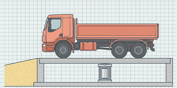
Weighing modules are the workhorses of industrial weighing – but when they fail, production stops, quality suffers, and costs escalate. According to industry surveys, 49% of plants cite calibration complexity as a major pain point, 43% struggle with unplanned maintenance downtime, and 38% face integration issues that complicate troubleshooting. This guide is written for field technicians and plant maintenance teams: it provides hands‑on solutions for the three most common weighing module failures – signal drift, support screws left tightened, and junction box moisture – plus welding protection, calibration best practices, and a preventive maintenance checklist.
Industry Challenges at a Glance
49%
calibration complexity
43%
unplanned maintenance downtime
38%
integration issues
These statistics highlight the need for a systematic, hands‑on approach to weighing module maintenance. The following failures represent over 80% of field service calls – and each can be resolved or prevented with the right knowledge.
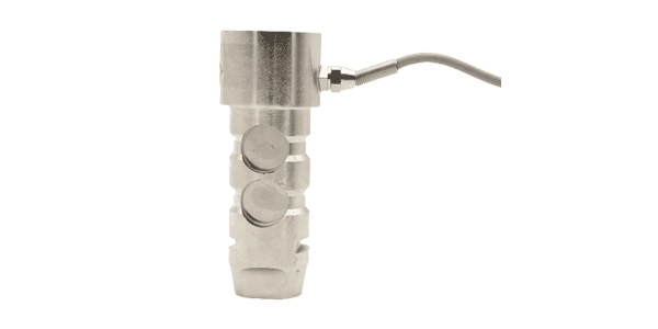
Failure 1: Signal Drift (Zero or Span Drift)
🔍 Symptoms
Reading slowly changes with no load applied (zero drift).
Sensitivity changes – weight readings are inconsistent at different loads.
Drift correlates with temperature changes or time of day.
⚙️ Common Causes
Temperature effects: Rapid ambient changes or gradients across the module.
Moisture ingress: Reduced insulation resistance due to water in the load cell or cable.
Improper mounting: Binding, side loads, or uneven support creating mechanical stress.
Overload damage: Permanent deformation from shock loads.
🛠️ Step‑by‑Step Fix:
Check environmental conditions: Use a thermometer to monitor temperature changes. Install a heat shield if radiant heat is present.
Perform insulation resistance test: Disconnect the module and measure between signal wires and shield/ground at 500V DC. Healthy >5000 MΩ. If <20 MΩ, moisture has penetrated – replace module.
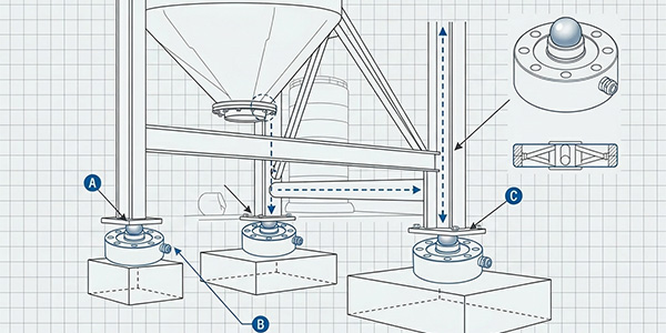
Inspect mounting: Verify that the module is not binding. Loosen limit bolts to 1–2 mm clearance. Ensure the vessel foot makes full contact with the top plate.
Zero the system after warm‑up: Allow 30–60 minutes for thermal stabilization before re‑zeroing.
If drift persists: Replace the module; recalibrate the system.
💡 Pro Tip: Log zero readings over several days to identify patterns. Drift that follows temperature cycles suggests a thermal compensation issue; drift that worsens over time suggests moisture ingress.
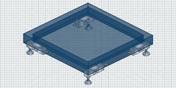
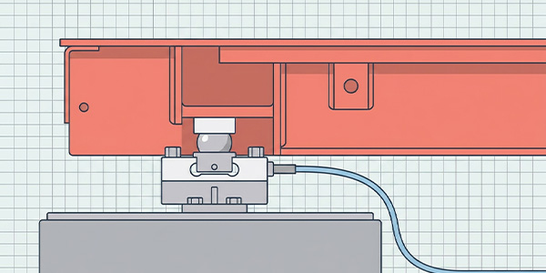
Failure 2: Support Screw Not Loosened
This is the single most common installation error – and the easiest to fix.
🔍 Symptoms
No weight reading or reading stuck near zero.
Reading changes very little when load is applied.
Non‑repeatable readings.
⚙️ Cause
Most weighing modules are shipped with transport support screws or ground bolts that lock the load cell’s moving part during shipping. If these screws are not loosened or removed after installation, the load cell cannot deflect – it cannot measure force.
🛠️ Step‑by‑Step Fix:
Identify the support screw(s) on the module – typically a bolt through the top plate or a set screw on the side.
Using the appropriate tool, back off the screw until there is a visible gap (usually 1–2 mm) or remove it entirely if specified by the manufacturer.
Verify that the top plate moves slightly when pressed (manual check).
Perform a zero calibration and test with a known weight.
⚠️ Critical: Some modules have two sets of screws – shipping bolts and limit bolts. Shipping bolts must be completely removed; limit bolts should be adjusted to provide 1–2 mm clearance. Always consult the installation manual.
After loosening, the module should immediately respond to load changes. If not, check for other binding issues.
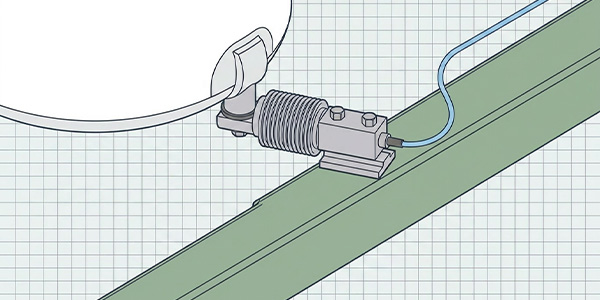
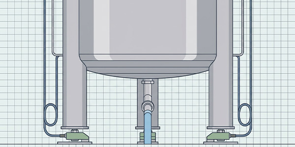
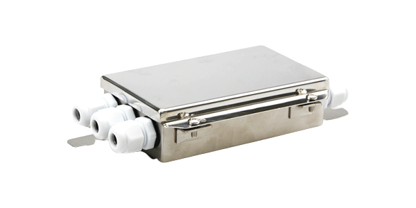
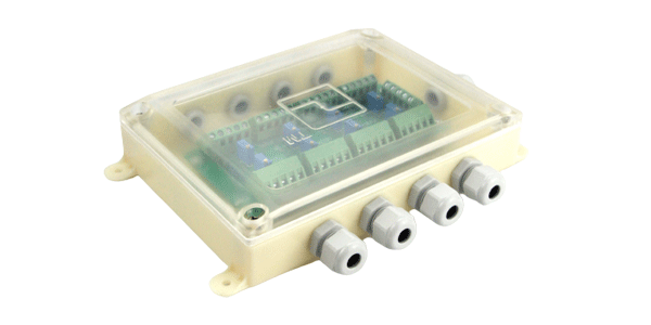
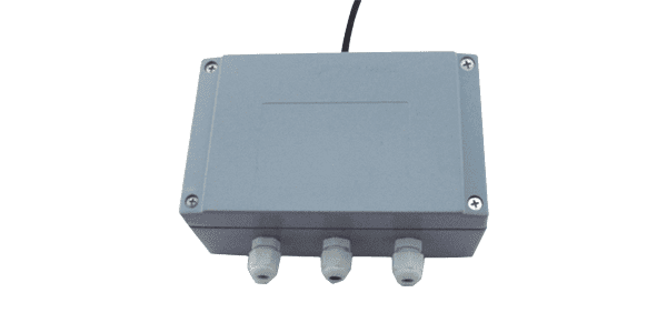
Failure 3: Junction Box Moisture
Junction boxes (summing boxes) are often located in humid or washdown environments. Moisture is their enemy.
🔍 Symptoms
Erratic, jumping weight readings.
Readings change when cables are moved.
Intermittent overload or underload alarms.
Visible condensation inside the junction box.
⚙️ Causes
Poor sealing of cable entries (glands not tightened).
Missing or damaged gasket on the cover.
Condensation due to temperature cycling.
Direct water spray (if IP rating insufficient).
🛠️ Step‑by‑Step Fix:
Disconnect power to the system.
Open the junction box and inspect for moisture, corrosion, or white residue.
Dry the interior with compressed air (oil‑free) or a low‑heat dryer. Replace any corroded terminal blocks.
Install a desiccant pack inside the box to absorb residual humidity.
Check all cable glands – tighten them firmly. Ensure no gaps around wires.
Replace the gasket if damaged; apply dielectric grease to the sealing surfaces.
If the box is repeatedly wet, upgrade to a higher IP rating (IP67 or IP68) or relocate the box to a drier area.
💡 Prevention: Use junction boxes with IP66/IP67 rating, install them with cable entries facing downward, and add breather drains if condensation is unavoidable.
Prevention During Welding: Protecting Load Cells from Current Damage
Welding on the vessel or structure while load cells are connected is a common cause of sudden, catastrophic failure. The high welding current can travel through the load cell, destroying the strain gauges and compensation resistors.
⚠️ Rule #1: Never weld on a vessel or structure that is supported by load cells without first disconnecting the load cells or providing an alternative current path.
🛡️ Safe Welding Procedure:
Disconnect the load cells: Unplug the cables from the junction box or indicator. This removes the electrical path through the sensor.
Ground the welder directly to the workpiece: Attach the welder’s ground clamp as close as possible to the welding point – on the same structural member. Never allow current to travel through bearings, pivots, or load cells.
Isolate the weighing system: If disconnection is impossible, install temporary grounding straps that bypass the load cells. Ensure these straps have a current capacity greater than the welder’s maximum output.
After welding: Reconnect the load cells and verify zero balance and calibration before returning to service.
📋 Checklist for Welders: ☐ Load cells disconnected?
☐ Ground clamp within 1 meter of weld?
☐ No current path through load cells?
☐ Post‑weld verification performed?
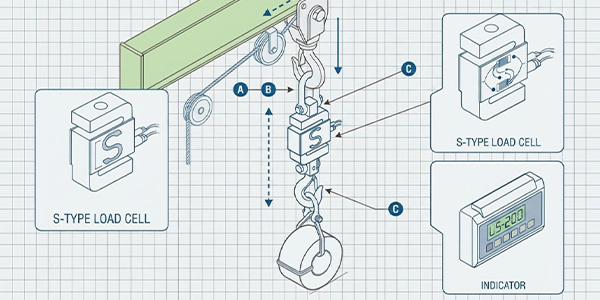
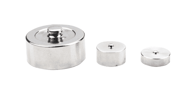
Calibration Best Practices: Using Test Weights Correctly
Proper calibration ensures accuracy and legal compliance. Follow these guidelines:
Use certified test weights: Traceable to national standards (NIST, OIML).
Minimum weight: At least 20% of the scale’s capacity for a two‑point calibration; for high accuracy, use 50–100%.
Apply weights evenly: For multi‑module systems, distribute the test weight to simulate actual loading.
Allow warm‑up: Power on the indicator for at least 30 minutes before calibration.
Perform a corner test: For platforms or tanks, place test weight over each module to verify consistent readings (adjust corner trimming if needed).
Record results: Keep calibration certificates and logs for audit purposes.
📊 Calibration frequency: Annually for most industrial applications; semi‑annually for legal‑for‑trade or harsh environments; after any module replacement, impact event, or significant temperature change.
Preventive Maintenance Checklist
Monthly visual inspection: Check for loose bolts, damaged cables, corrosion, or debris around modules.
Monthly zero check: Record no‑load reading. If drift exceeds ±0.1% of full scale, investigate.
Quarterly limit bolt check: Verify 1–2 mm clearance on all lateral limit bolts.
Quarterly junction box inspection: Open and check for moisture, corrosion, and tight connections.
Semi‑annual insulation test: Measure resistance between signal wires and shield. Document values.
Annual calibration: Perform full calibration with certified test weights.
Event‑based: After any overload, lightning strike, or welding, re‑zero and verify calibration.
Use a digital logbook to track these activities – trending data helps predict failures before they occur.
When to Call a Specialist
While many issues can be resolved in‑house, some situations require expert intervention:
Physical damage to load cell: Cracks, dents, or deformed structure – replace immediately.
Persistent non‑repeatability: After checking mounting and connections, internal damage may be present.
Legal‑for‑trade calibration: Must be performed by a certified technician using traceable weights.
Integration with new PLC/indicator: Specialist ensures correct parameters and scaling.
At Galoce, our field service engineers are available for on‑site troubleshooting, calibration, and training. Request Technical Support
Conclusion: Proactive Maintenance = Maximum Uptime
Most weighing module failures are preventable. Signal drift, support screws left tightened, and junction box moisture account for the vast majority of field issues – and each has a straightforward fix. By following the preventive maintenance checklist, training your team on proper installation (especially loosening transport screws and welding protection), and calibrating regularly, you can reduce unplanned downtime from 43% to under 5%.
Remember: a weighing module is a precision instrument. Treat it with care, document your inspections, and never guess – measure. When in doubt, consult the manufacturer or a certified specialist.
Galoce provides comprehensive technical documentation, online troubleshooting tools, and global field support to keep your weighing systems running at peak performance.
Discover why GALOCE is the leading load cell manufacturer in China. Offering high-precision force sensors, 26-step quality audits, and global OEM/ODM engineering for US & UK industrial standards. Explore our brand guide.
Master industrial load cell installation with our 2026 handbook. Learn step-by-step mechanical mounting, cable routing, and professional calibration for tension and compression sensors to ensure accuracy and system longevity with GALOCE.